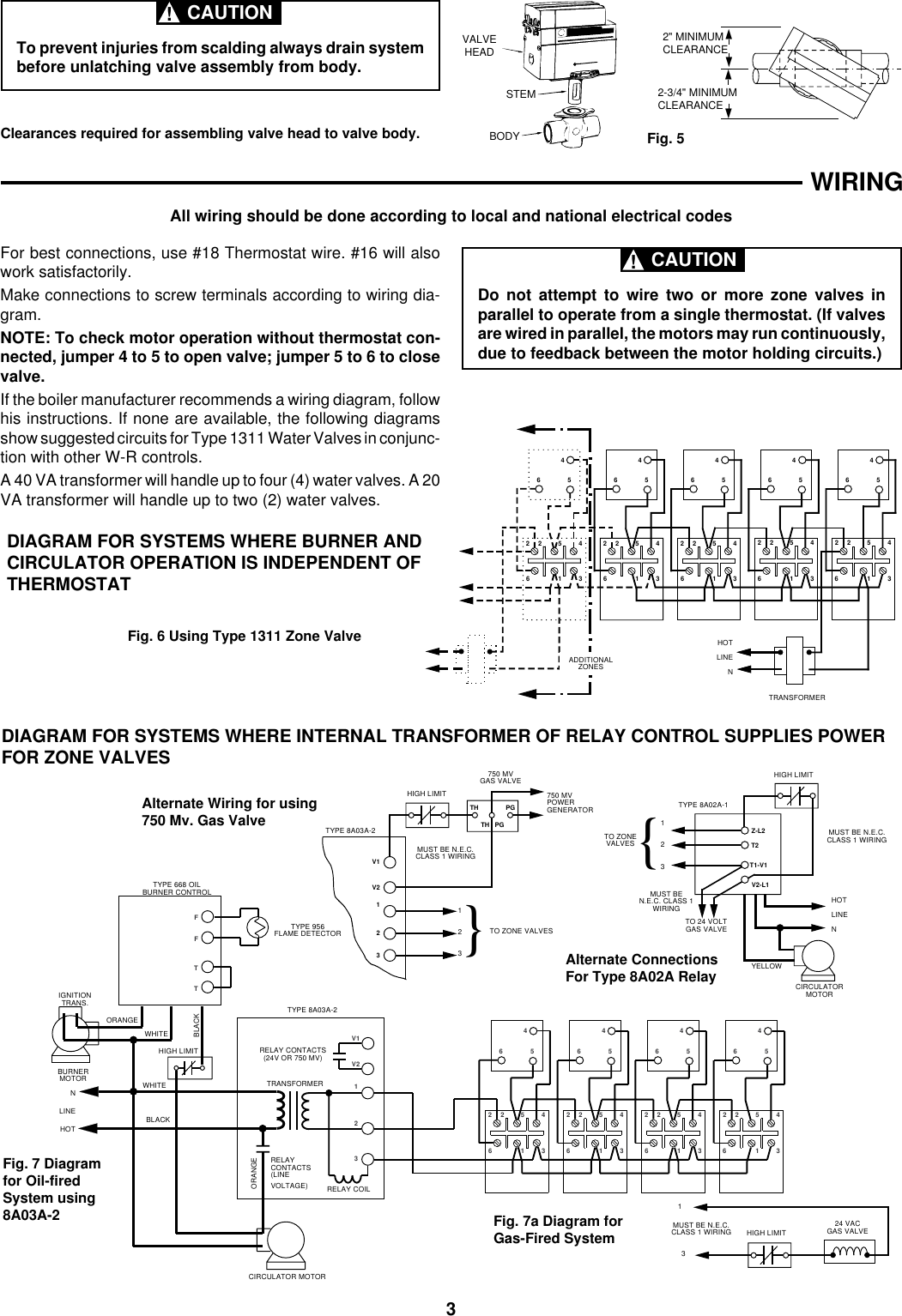
White Rodgers 1311 Zone Valve Wiring Diagram
Tempstar Furnace Control Board Wiring Diagram, Tempstar ICP Gas Furnace Circuit Board Replaced, 38.06 MB, 27:43, 22,381, Anti DIY HVAC, 2020-09-10T01:38:43.000000Z, 19, Tempstar Tca030aka1 Wiring Diagram, wiringall.com, 800 x 600, jpeg, tempstar, 20, tempstar-furnace-control-board-wiring-diagram, Anime Arts
Wiring diagram rodgers 1311 zone valve. White rodgers 90 113 wiring diagram wiringall. com. Wiring rodgers steveco l39 rbm furnace johnstone honeywell. The white rogers zone valves have three wires, white red and green.
White rodgers 50a50 241 wiring diagram diagramweb. net. White rodgers thermostat wiring diagram 1f89 211 diagramweb. net. Rodgers thermostat 1f89 np110 honeywell thermostats. Valve zone rodgers 1311 list sweat wire three. Valve head stem body fig. 5 diagram for systems where burner and circulator operation is independent of thermostat fig. Class 1 wiring must be n. e. c. White rodgers 1311 {, }. Valve head stem body fig.
White Rodgers 1311 Photo by Houston204 | Photobucket
White Rodgers 1311 Wiring Diagram - Wiring Diagram

White Rodgers 1311 102 Wiring Diagram | Free Wiring Diagram

White Rodgers 1311 102 Wiring Diagram | Free Wiring Diagram

White Rodgers 1311 Wiring Diagram - Wiring Diagram

[Download 24+] White Rodgers 1311 Zone Valve Wiring Diagram
![White Rodgers 1311 Zone Valve Wiring Diagram [Download 24+] White Rodgers 1311 Zone Valve Wiring Diagram](https://usermanual.wiki/White-Rodgers/WhiteRodgers1311103HydronicZoneControlsInstallationInstructions676703.278256608-User-Guide-Page-4.png)
White Rodgers Zone Valve Wiring Schematic - Wiring Diagram

White Rodgers 1311 User Manual

White Rodgers 1311 102 Wiring Diagram | Free Wiring Diagram

White Rodgers 1311 Wiring Diagram - Wiring Diagram

